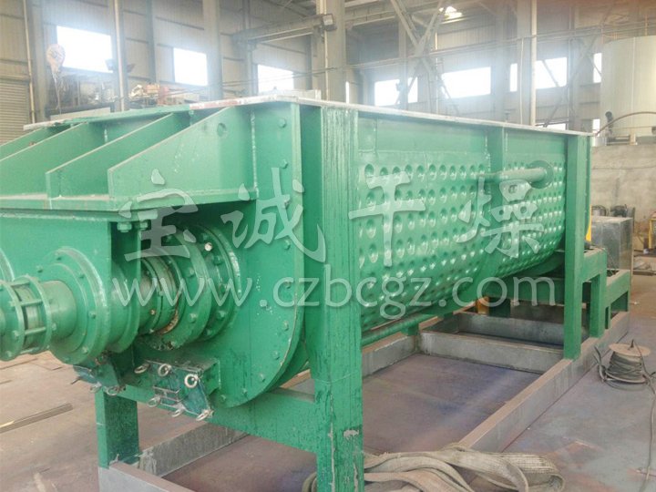
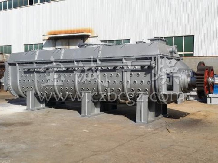
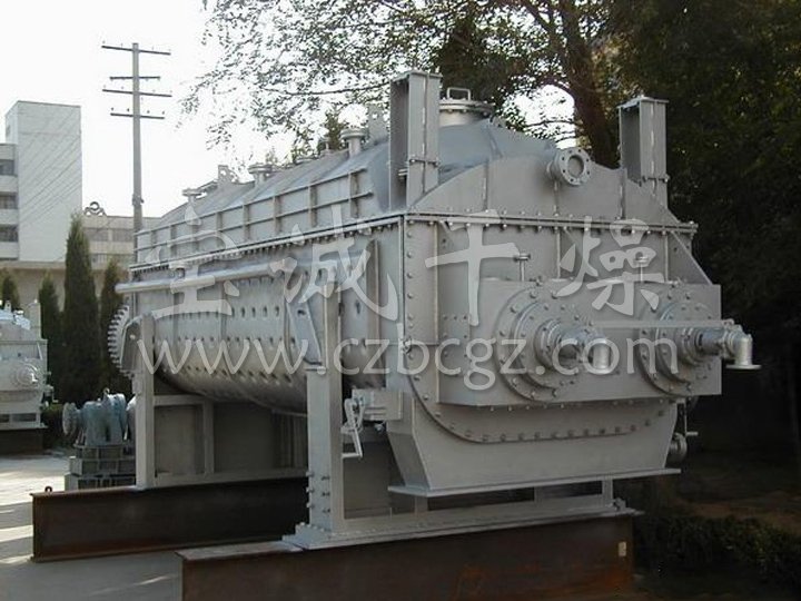
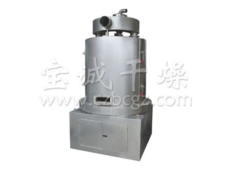
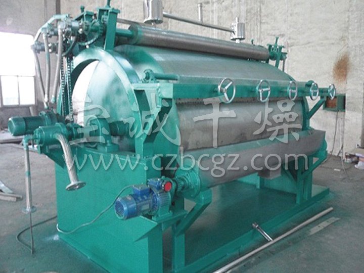
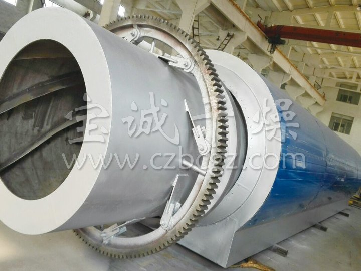
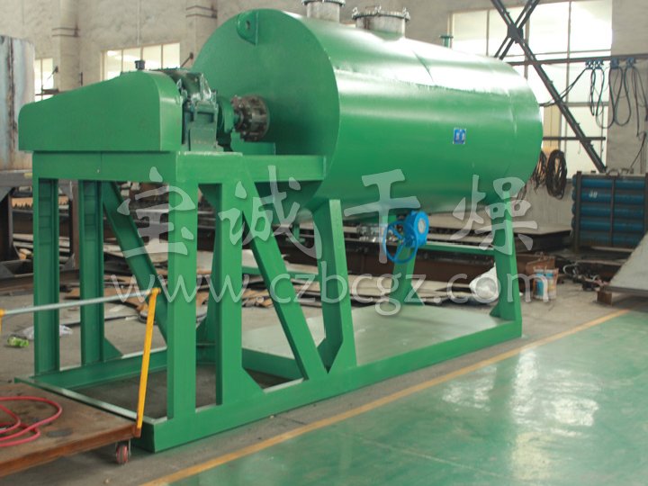
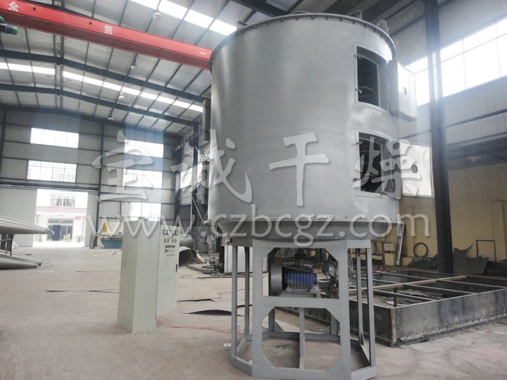
JYG Hollow Blade Dryer
DESCRIPTION
Dual counter-rotating shafts with unique intermeshing hollow wedge-shaped paddles produce intimate mixing, optimize heat transfer, and provide a self-cleaning feature. A large heat transfer area to volume ratio is achieved by the use of hollow paddles and a jacketed vessel, through which the heating medium flows. The result is an efficient, compact machine with less space requirements and lower installation cost.
WORKING PRINCIPLE
The Hollow Paddle Dryer has a metal wall which separates the process mass from the heat source (steam or hot oil). High thermal efficiency is obtained because the heat from the thermal medium goes directly into the process mass. As the material comes into contact with the heated through and agitators, the process mass is heated via conduction. With an insulated dryer, very little heat is lost. To evaporate 1kg of water only requires about 1.2kg of steam for slurry materials. Exhaust gas is minimal and at a low temperature. Therefore, the volume of non-condensable gas from the dryer, which might require treatment, is minimal.
The dryer is an indirect heat transfer device which utilizes a high degree of mechanical agitation to enhance contact with the product being dried. Evaporation rates per square foot of heat transfer surface are maximized through self-cleaning paddles and the mixing effect. Movement of the process material between the slanting surfaces of the revolving wedge-shaped paddles generates shearing forces, which clean the paddle surfaces and maximize conductivity. Counter rotating shafts move the material away from the walls, cleaning the walls by means of the tab on each paddle. This results in higher heat transfer rates than disc or single shaft designs. The wedge-shaped paddles, and the intermeshing of the dual agitators, create a localized mixing effect around the paddle. This allows more individual particles in the bed to be exposed directly to the heat transfer surface, thereby increasing the heat transfer rate, allowing the use of smaller equipment.
HEAT SOURCES(Temperature at 180°C - 250°C)
Heating by Steam
Steamenters the hollow shaft through a rotary joint and is evenly distributed to all paddles. Condensate is removed with each revolution. Heating by Hot Oil (thermal fluid) Hot oil (thermal fluid) enters and exits the hollow shaft through a rotary joint. Pressure from the supply pump forces liquid through the hollow paddles.
FEATURES
Low Operation Cost
- Easy to operate
- Requires minimal attention
- Simple instruments monitor the process
- High efficiency
- Low off-gas volume
Low Installation Cost
- Designed with compact structure
- Small off-gas system
- Vertical shaft removal reduces building size requirements
Low Maintenance Cost
- Designed for high torque and low operating speed
- Simple durable design for easy and low maintenance
- No internal parts to adjust or maintain
- No metal to metal contact
- Shafts, pillow block bearings, and drive components are designed for long life under adverse conditions, insuring long term mechanical integrity
- Robust frame supports split pillow block bearings
- Grease-purged stuffing boxes. Alternate seal designs are available
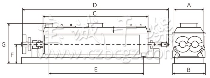
TECHNICAL PARAMETERS
| Item \ Model | JYG3 | JYG9 | QJ13 | JYG18 | JYG29 | JYG41 | JYG52 | JYG68 | JYG81 | JYG95 | JYG110 |
| heat transferring area (m2) | 3 | 9 | 13 | 18 | 29 | 41 | 52 | 68 | 81 | 95 | 110 |
| effective volume (m3) | 0.06 | 0.32 | 0.59 | 1.09 | 1.85 | 2.8 | 3.96 | 5.21 | 6.43 | 8.07 | 9.46 |
| range of rotating speed (rmp) | 15-30 | 10-25 | 10-25 | 10-20 | 10-20 | 10-20 | 10-20 | 10-20 | 5-15 | 5-15 | 5-10 |
| power (kw) | 2.2 | 4 | 5.5 | 7.5 | 11 | 15 | 30 | 45 | 55 | 75 | 95 |
| width of vessel (mm) | 306 | 584 | 762 | 940 | 1118 | 1296 | 1476 | 1652 | 1828 | 2032 | 2210 |
| total width (mm) | 736 | 841 | 1066 | 1320 | 1474 | 1676 | 1854 | 2134 | 1186 | 2438 | 2668 |
| lenght of vessel (mm) | 1956 | 2820 | 3048 | 3328 | 4114 | 4724 | 5258 | 5842 | 6020 | 6124 | 6122 |
| total lenght (mm) | 2972 | 4876 | 5486 | 5918 | 6808 | 7570 | 8306 | 9296 | 9678 | 9704 | 9880 |
| distance of material inlet& outlet (mm) | 1752 | 2540 | 2768 | 3048 | 3810 | 4420 | 4954 | 5384 | 5562 | 5664 | 5664 |
| height of center (mm) | 380 | 380 | 534 | 610 | 762 | 915 | 1066 | 1220 | 1220 | 1220 | 1220 |
| total height (mm) | 762 | 838 | 1092 | 1270 | 1524 | 1778 | 2032 | 2362 | 2464 | 2566 | 2668 |
| steam inlet (inch) | 3/4 | 3/4 | 1 | 1 | 1 | 1 | 11/2 | 11/2 | 11/2 | 11/2 | 2 |
| water outlet (inch) | 3/4 | 3/4 | 1 | 1 | 1 | 1 | 11/2 | 11/2 | 11/2 | 11/2 | 2 |
- 2017-06-13 > How do we know the tank mixer?
- 2017-06-13 > Induction hot air circulation oven production characteristics
- 2017-02-27 > The working principle of double cone back vacuum dryer
- 2017-02-23 > Operation of double cone rotary vacuum dryer
- 2017-02-20 > Introduction of Double Cone Rotary Vacuum Dryer
- 2017-02-17 > Advantages of Double Cone Rotary Vacuum Dryer
- 2016-08-15 > Double cone rotary vacuum dryer with counterweight adjustment range

